X

Thermal contact resistance


The thermal contact resistance characterizes the transfer of heat at the interface between two solids. Due to the manufacturing and machining processes, but also its intrinsic material property, roughness at the surface is unavoidable. As a result, not the entire surface of the two solids is in direct contact, but only a fraction and accordingly not involved in heat transport. The resulting voids between the solids are usually filled with air, a poor conductor of heat.[1,2] A temperature jump at the interface is the result. The following applies to the specific thermal contact resistance:[1]

with
rK: specific thermal contact resistance in (m2K)/W
A: nominal (macroscopic) contact area without roughness in m2
Q ̇: Heat flow through the contact area A in W
ΔT: Temperature jump at contact surface A in K.

Its reciprocal value is also referred to as the thermal contact coefficient. The quotient of the specific thermal contact resistance rk and the macroscopic contact area A is called the thermal contact resistance:

The unit of thermal contact resistance is □(K/W).

What can influence the thermal contact resistance?

  • Surface roughness of solids
  • Contact pressure on the contact surface between the two solids
  • Filling the voids between contact surfaces with better thermally conductive materials, such as: gels, pastes, phase change materials, foils, adhesives, thermal interface materials, etc.
  • In general, the combination of the two solids determines the thermal contact resistance

A highly simplified model for calculating the thermal contact resistance can be set up using a resistance model. The heat flow is split into solid and fluid components and treated separately. In the solid path there are two resistors connected in series. The portion through the fluid is formed by the enclosed air. Heat transport takes place in parallel through both channels, which is why it can be represented as a parallel circuit in the equivalent circuit diagram. (cf. Figure 1)

Figure 1: Highly simplified model for determining the thermal contact resistance [1].

Figure 1: Highly simplified model for determining the thermal contact resistance [1].

With the help of the equivalent circuit diagram and the known rules for calculating the resistance in series and parallel connection, the following formula [1] is obtained:

with

Thermal resistance of the materials 1,2 or of the air in K/W
It is valid

δ: Thickness of the boundary layer in m
λ_(1,2,Air): Thermal conductivity of materials 1, 2, respectively of the material in the gap (generally air) in W/(m K)
A: nominal (macroscopic) contact area without roughness in m^2
φ: Proportion of solid contact area to nominal area A

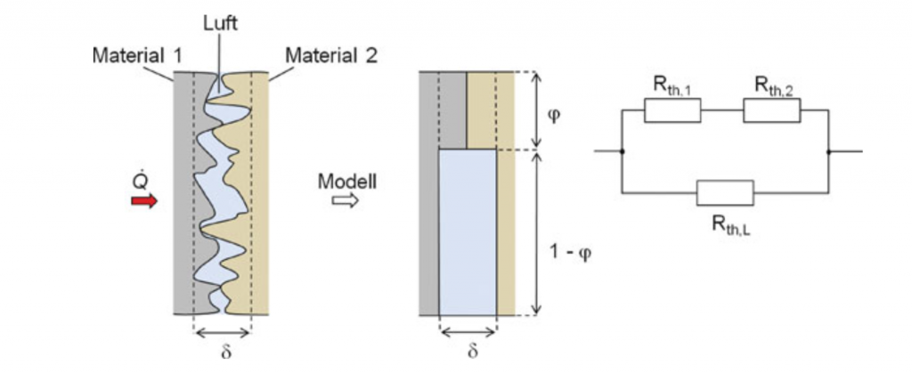
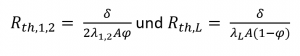
The model has some weak points. Firstly, it does not take the heat transfer in the form of radiation into account and secondly, the boundary layer thickness δ and the part of the nominal area which participates in the heat transfer φ is known only in the rarest cases.

How do I measure the thermal contact resistance?

The thermal contact resistance can be determined, for example, with the aid of a “Thermal Interface Material Tester” (TIM tester). A TIM tester measures the thermal impedance of a material for different thicknesses by applying a heat flux through the sample. Further details on the principle of operation can be found on our website. [3] An increasing straight line can be determined from the measurement points via a linear regression, and the thermal conductivity can be determined from its slope. The intercept of the straight line corresponds to the thermal contact resistance between the material and the measuring block. For instance, the meter bar can be made of brass or a copper or aluminium alloy. An example of such a measurement is shown in Figure 2. It is a measurement of the thermal impedance of a VespelTM sample with a size of 25 mm x 25 mm and an applied contact pressure of 1 MPa. In the example, samples with a thickness between 1.1 mm and 3.08 mm were measured.

Figure 2: Measurement of thermal conductivity of VespelTM (at 50°C, 1MPa)

Figure 2: Measurement of thermal conductivity of VespelTM (at 50°C, 1MPa)

Literature:
[1] Griesinger, Andreas. Wärmemanagement in der Elektronik, Springer Berlin Heidelberg, 2019.
[2] Incropera, DeWitt, Bergmann, Lavine, Fundamentals of heat and mass transfer.pdf“, John Wiley & Sons, 2017.