

DC and AC Hall Effect Measurements
The investigation of the Hall effect of a material is specially used for the determination of the Hall coefficient as well as the carrier concentration, the carrier type and mobility. By that one can evaluate and optimize the performance of the used materials in an electronic device, e.g. in the thermoelectric technology, solar cell technology or in organic electronics.
The Hall effect appears when a magnetic field is applied perpendicular to a current flowing conductor and it describes the phenomenon that a voltage is created which is perpendicular to both the direction of current flow and the magnetic field. The voltage is called Hall voltage, usually VH, and can be calculated by
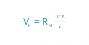
where RH is the material dependent Hall constant, I is the strength of the current through the conductor, B is the magnetic field strength and d is the thickness of the conductor parallel to the magnetic field direction.
The sign of the hall voltage indicates the type of charge carriers and the carrier concentration n can be determined via with e denoting the elementary charge. Using the Hall constant RH and the electrical resistivity ρ, also the mobility µ can be calculated. Ideally, with no applied magnetic field the Hall voltage should be zero, but in reality, it turns out that a small offset voltage can be detected, which contributors are a misalignment voltage VMA and a thermoelectric voltage VTE. The misalignment voltage is proportional to the resistivity and the current and depends on the sample geometry.
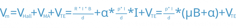
For example, in a Van-der-Pauw configuration, the ideal configuration would be four point contacts on the corner of a perfectly uniform square sample. The misalignment factor and voltage would be zero, however, in practical measurements there are typically deviations from the ideal case. Furthermore, as during measurements two materials are brought into contact, i.e. the material and the contact-material, thermoelectric effects appear which result in the thermoelectric voltage offset contribution. So that the measured voltage Vm will result in the following equation, where α is the so-called misalignment factor.
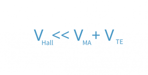
so that the DC field measurement method comes to its limits, as it will be extremely difficult to extract the small Hall voltage from the total measured voltage.
For this case, the AC method became an established method which is offering better solutions studying the properties of low mobility materials. Since the Hall voltage is proportional to the magnetic field, the hall voltage generated by an AC magnetic field will be also an AC signal.
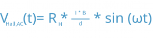
Advantageous is that the misalignment voltage and the thermoelectric voltage do not depend on the magnetic field and are thus DC voltages, so that they can be separated rather easily. In the experiment, using a lock-in-amplifier in the measurement electronics allows the precise separation of the desired AC signal from the undesired DC signal. But there is a new term in the measured voltage which is proportional to the time derivative of the magnetic field and to the inductance of the sample as well as the leads used in the measurement. The measured voltage can then be written as

where β denotes the proportionality constant. Since the new term is independent of the current, it can be removed with current reversal. Additionally, it is also 90° out of phase of the AC signal, so that a phase resolution on the lock-in-amplifier can eliminate this new term.

In conclusion, with the AC method one can determine mobilities in the range as low as 10-3 cm2/Vs, which is a factor 1000 lower compared to the DC field method. This is especially beneficial in the fields of photovoltaic and alternative energy applications, as well as organic electronic materials.


