X

Van-der-Pauw measurement

The Van der Pauw measurement method, named after its inventor Leo J. van der Pauw, is a widely used as a 4-point measurement for determining the sheet resistance and the Hall coefficient of materials.

In 1958 van der Pauw solved the general problem of potential distribution in a thin, conductive layer of any shape and thus made it possible to carry out Hall and resistance measurements on them. However, some prerequisites must be met for a correct measurement. The thickness t of the sample must be homogeneous and small in relation to the distance between the contacts. It must consist of a continuous form in the mathematical sense and must therefore not have any holes or islands made of highly conductive material. The four contacts must be on the edge of the sample and small in relation to the area of ​​the sample.

Van der Pauw method

Fig. 1) Experimental setup for Van-der-Pauw measurement

Contacting of a sample for the Van-der-Pauw measurement

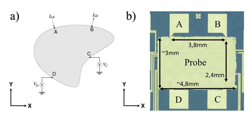
Fig. 2 a) Contacting of a sample for the Van-der-Pauw measurement. b) Contacting the sample on the TFA measurement chip, including its dimensions.
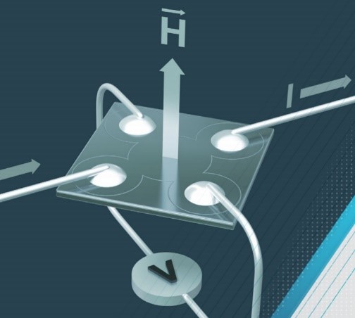
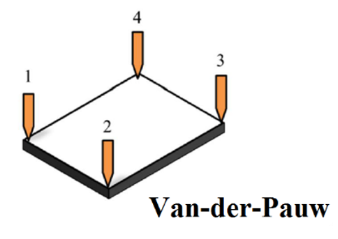
If all the requirements are met, a sample prepared with the edge contacts A, B, C and D is obtained, as shown in Fig. 2a-b. To calculate the electrical conductivity, horizontal and vertical Van der Pauw resistances R(ij,kl), must be measured, whereby the following applies to the measurement of the horizontal resistance:

horizontal resistance

Where VC  is the voltage of the contact measured against ground and IAB is the current applied between the contacts A and B, starting at A and ending at B. If the contacts are changed cyclically, the vertical Van der Pauw resistance can be determined. If the horizontal and vertical resistance have been measured, the surface resistance or, if the layer thickness is known, the resistivity can be calculated by numerically solving the Van der Pauw formula:

resistivity formula van der pauw

As the electrical conductivity  is the reciprocal of the specific resistance , it can be calculated according to the following equation.

electrical conductivity

To determine the Hall coefficient of the sample, an external magnetic field with the flux density BZ can be applied perpendicular to the surface of the sample and the change in the diagonal Van der Pauw resistance (see Fig. 3), depending on the magnetic field strength, is measured.

sample configuration Hall coefficient measurement using Van der Pauw technology

Sample configuration for the Hall coefficient measurement using Van der Pauw measurement technology, with an applied magnetic field perpendicular to the sample surface.

In the case, the following is valid:

Hall formula

such as

with the Hall coefficient AH and the magnetic flux density BZ. Offset effects in current and voltage measurement can be suppressed according to the principle of measurement direction inversion. Offset effects coming from the magnetic field strength measurement, are suppressed by measuring the diagonal voltage VHall  at different magnetic field strengths and determining the Hall coefficient from the slope of the Hall voltage over magnetic field strength. The final calculation is done according to the following equation:

Voltage Hall formula
If the Hall constant is measured using the AC measurement method, an alternating magnetic field is applied and the resulting Hall voltage is read out using a lock-in amplifier. As a result, materials with particularly low mobilities can be still be measured, since the usually small Hall voltages are no longer superimposed by so-called misalignment offsets.

What properties are determined?

The Van-der-Pauw method is used to determine the electrical transport properties of materials (bulk and thin films) like the electrical conductivity, the resistivity, the hall constant, the charge carrier concentration and the charge carrier mobility.