

The charge carrier mobility in semiconductor materials is an important parameter for solar cell usability. Light falling on a solar cell generates free charge carriers which produce an electrical voltage on the electrodes. The mobility of charge carriers in the material determines the current flow in the cell and thus influences its usable output.
Semiconductors used in photovoltaic systems naturally exhibit low mobility; for polycrystalline silicon in solar cells, it is 1,000 to 10,000 times smaller than for high-purity silicon, which is required in component manufacturing.
The mobility of charge carriers in semiconductors can be measured using the Hall effect as per the ASTM F76-08 standard. The type (electrons or holes) and the density of the charge carriers as well as the mobility of these in the material can be determined via a resistance measurement. While measurement in a constant magnetic field (DC) is widespread, it is unsuitable for the accurate measuring of materials with low mobility, such as those relevant for solar cell technology, thermoelectrics or organic electronics.
Hall effect and measurement
Edwin Herbert Hall discovered the Hall effect named after him in 1879. He observed that the current in a conductor can be influenced by an external magnetic field.
If a current-carrying (semi) conductor is perpendicularly penetrated by a magnetic field, the Lorentz force causes a force component that acts perpendicularly to the direction of movement of the charge, so that charge carriers are deflected onto a circular path. This creates a concentration gradient of charge carriers within the conductor across the current direction. There is a lack of electrons on one side of the conductor and an accumulation of charge carriers on the opposite side. The resulting voltage is referred to as Hall voltage UH. It depends on the current intensity I, the magnetic flux density B, the thickness of the sample d and a material constant, the Hall coefficient AH.
Equation 1:
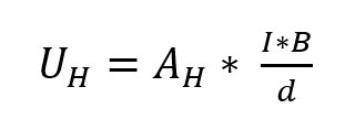
If the Hall coefficient has a positive value, it is a “hole conductor” (p-type); in most cases, a negative value means an electron conductor (n-type).
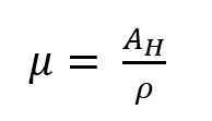
Equations 2 and 3 show further relationships between the Hall coefficient AH, the specific resistance ρ, the charge carrier density n and the mobility μ, where e is the elementary charge.
Equation 2:
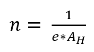
Equation 3:
Under real test conditions, the measured Hall voltage UHm can be influenced by an offset voltage component UO and a thermoelectric voltage component Uth. A special method was developed to eliminate the disruptive effects of the voltages UO and Uth. Thermal voltage can be eliminated by changing the current direction and then averaging the absolute values. The offset voltage results from the sample geometry; this can be compensated by reversing the magnetic field, because it does not depend on the field direction.
Since the DC method often leads to incorrect determination of the type of charge carrier and imprecise results for the mobility of low-mobility materials, an alternating magnetic field or an alternating current can be alternatively used. This is because while the Hall voltage becomes an alternating voltage, the direct voltage components UO and Uth can be suppressed. Small Hall voltages can be measured and materials with low charge carrier mobility can be characterized so that photovoltaic materials in particular can be evaluated using the AC method.


