


If a current-carrying semiconductor is placed in a magnetic field, the so-called Hall effect can be observed. It is caused by the Lorentz force, which acts on moving charge carriers in a magnetic field.
The Lorentz force moves the charge carriers in an arc perpendicular to the magnetic field lines. The accumulation of the deflected charge carriers on one side of the semiconductor creates an electric field that is perpendicular to the magnetic field and the direction of current flow.
The voltage of this field can be measured and is generally referred to as the Hall voltage VHall.

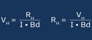
If the electric field of the Hall voltage and the Lorentz force are equal, a state of equilibrium is reached so that there is a proportional relationship between Hall voltage (VH), magnetic field (B) and current (I), which is known as the Hall coefficient (RH). This also depends on the thickness of the semiconductor (d).
The Hall coefficient can therefore be determined by measuring the Hall voltage for a given magnetic field and current and a known semiconductor thickness using the following formula:
Depending on the type of sample (p-type, n-type), a positive or negative Hall voltage results. If the transport is also dominated by one type of charge carrier, the charge carrier density n and mobility m of the sample can also be determined using the following formula:
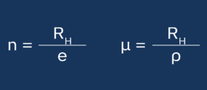
With e = charge of the charge carrier and ρ = specific resistance of the material.
The Linseis Hall measuring device can be used in a wide temperature range and is available with two different magnet types. You can choose between a permanent magnet, which measures at three fixed magnetic field strengths (+ field, 0 field and – field), and an electromagnet, which allows continuous magnetic field strengths.