Description
To the point
The characterization of micrometer materials is a critical issue today due to ongoing R&D for new technologies, such as battery and hydrogen applications, as well as miniaturization efforts.
Due to the large surface to volume ratio, these types of materials need to be studied separately from bulk materials, but sample preparation and measurements can be very challenging.
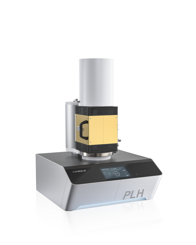
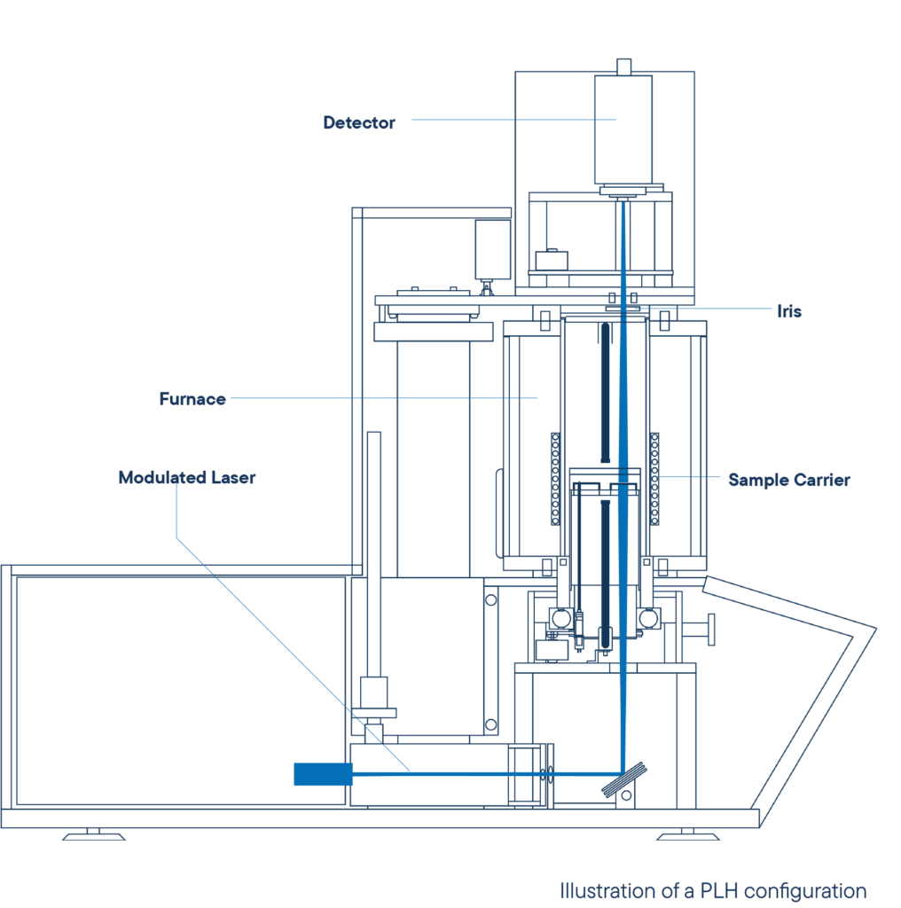
In addition to our well-established laser flash technique, the PLH L53 setup allows us to extend the measurement range of our non-destructive optical instruments in terms of thickness and thermal transport properties.
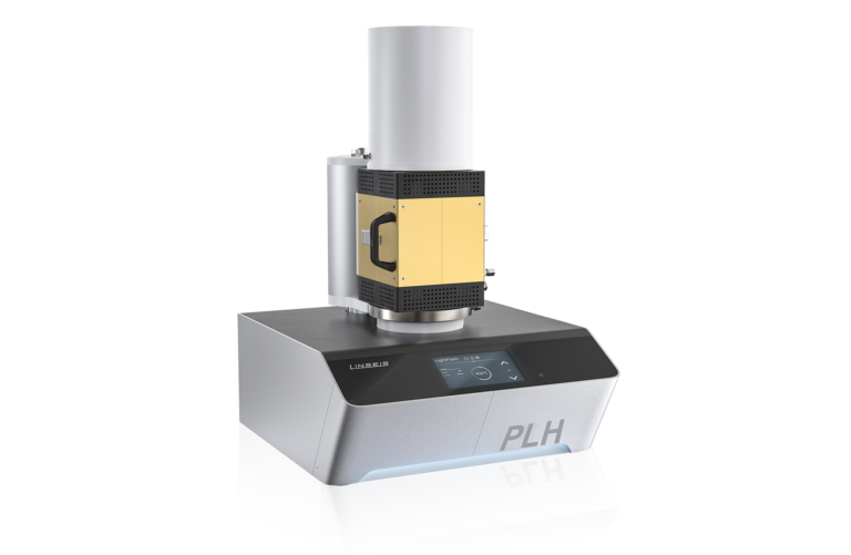
The PLH L53 has been developed and optimized to characterize samples with high accuracy over a measurement range of sample thickness from 10 μm to 500 μm and a thermal diffusivity range of 0.01 – 2000 mm²/s.
The system can handle a wide range of materials. It is possible to measure samples with semiconducting behavior as well as metals, ceramics or polymers. Typical applications include freestanding films and membranes for the battery and hydrogen industries.
Mode
Cross-Plane Periodic Laser Heating
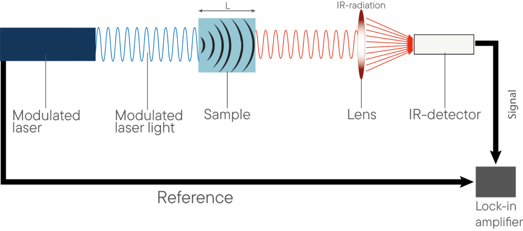
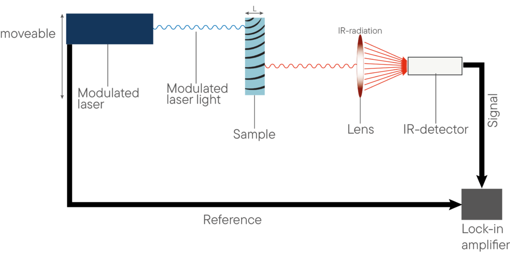
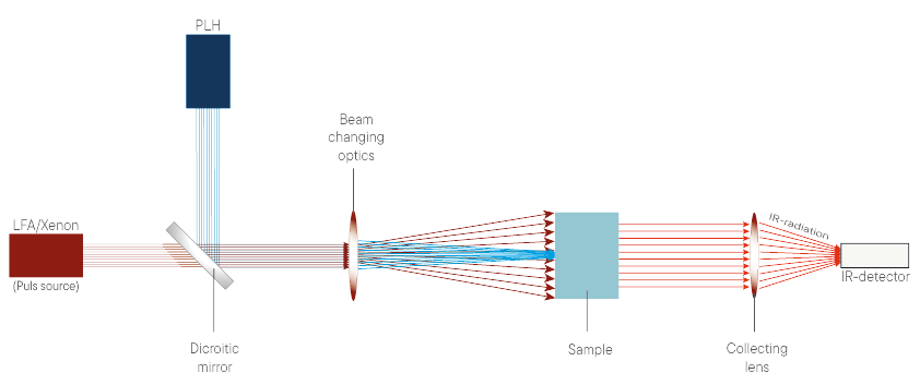
The system uses a diode laser to periodically heat the rear side of a sample with continuous amplitude modulated laser light. This energy is absorbed by the sample and induces a thermal wave. The thermal wave propagates through the sample to its front side, where the initially absorbed thermal energy is emitted. The resulting frontside temperature oscillation is recorded using an IR detector, as shown in the figure below.
Due to the thermal transport properties of the sample, a characteristic behavior of the phase shift and amplitude of the resulting signal can be observed.
Evaluation of thermal conductivity, thermal diffusivity, and volume specific heat capacity performed using our comprehensive Linseis software package. The only input parameter required is the sample thickness.
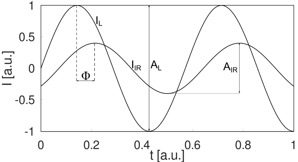
IL labels the modulated laser light and IIR is the infrared radiation with the corresponding amplitudes AL and AIR as well as the phase shift Φ.
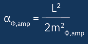
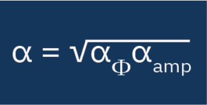
α = Thermal diffusivity [m2/s]
L = Sample height [m]
m = Slope of the linear range [√s]
Mode
In-Plane Periodic Laser Heating
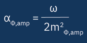

α = thermal diffusivity [m²/s]
ω = angular frequency (2*π*f ) [1/s]
f = modulation frequency [Hz]
m(Φ, amp) = slope of the two measurement curve once after phase and
once after amplitude [1/m]
Additionally, the system is capabale of measuring the in-plane thermal diffusivity through the use of a horizontal offset stage, while simultaneously exciting the sample with continous amplitude modulated laser light.
Depending on the in-plane thermal diffusivity of the sample, a characteristic behaviour of the measured phase shift and amplitude with respect to the lateral offset between laser and detector can be observed.
This methodology enables the intricate relationship between thermal conductivity and diffusivity to be elucidated, thereby yielding insights which may have significant implications for the landscape of material science.
Through precise in-plane measurements, thermal bottlenecks can be identified and optimal design solutions can be determined to enhance the performance and efficiency of technologies based on anisotropic materials. The evaluation of the in-plane thermal diffusivity can be performed using the comprehensive Linseis software package without knowing any other input parameters.
Anisotropy and inhomogeneity analysis
Anisotropy
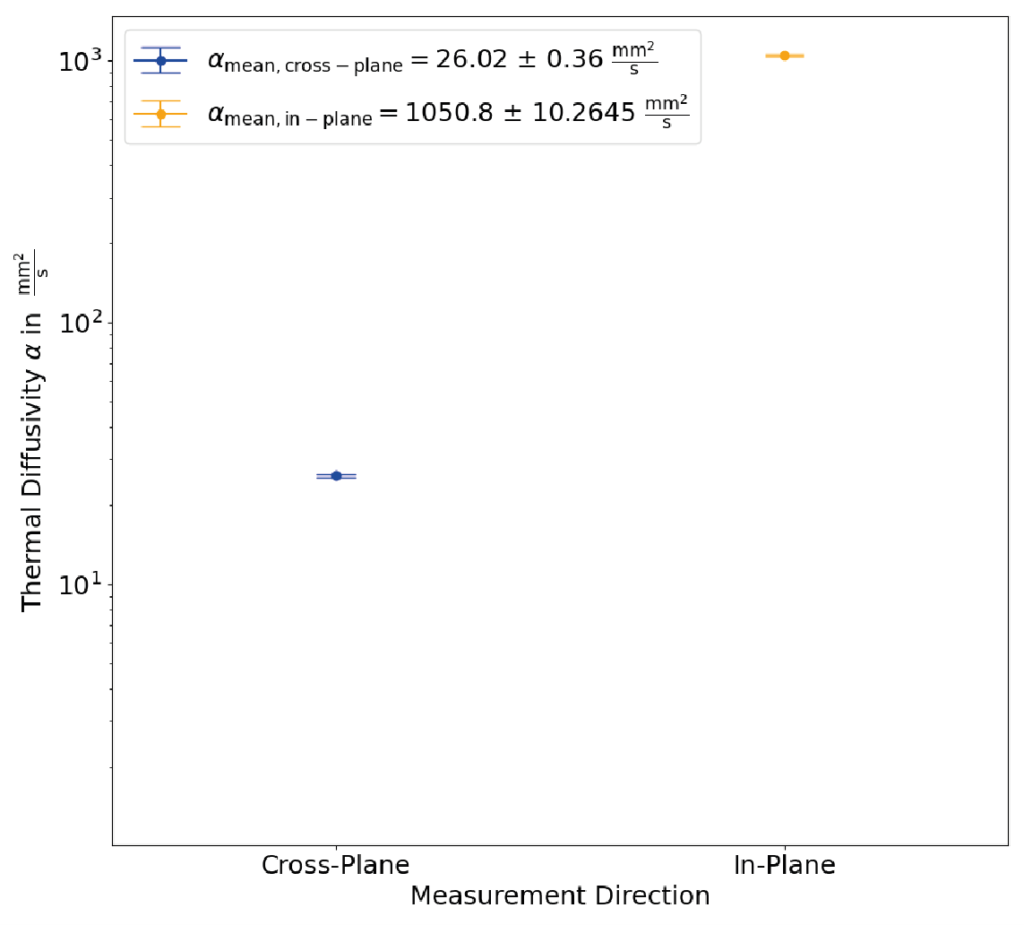
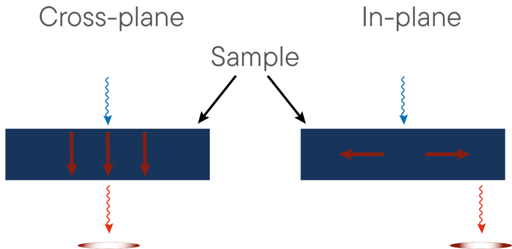
The thermal conductivity of the material can be direction-dependent. In-plane and cross-plane are terms used to describe two specific transport directions within a material, while in-plane actually means within the sample perpendicular to the direction of excitation, the term cross-plane refers to the thermal conductivity of the sample in the excitation direction.
The cross-plane and inplane thermal conductivities can significantly differ from each other and can easily exceed several orders of magnitude.
Use cases are versatile and its knowledge can be crucial in various applications such as electronic devices, where thermal management is a omnipresent challenge.
Inhomogenity
Depending on the sample, the composition may vary slightly across the sample.
This is normally the case for gels, pastes and polymers and so this change will also be seen in the thermal conductivity.
Typically, standard LFA instruments ignore this fact and consider the whole sample at once as it is heated up by the light pulse. When interested in this differences our PLH techniques comes in handy.
In contrast to the laser flash technique the sample is locally heated and you are able to check the sample for inhomogeneities.
Fluctuations in thermal conductivity can lead to hot spots that affect the performance and service life of electronic devices.
Ensuring homogeneous thermal conductivity distribution is crucial for effective thermal management and preventing overheating.
Unique Features
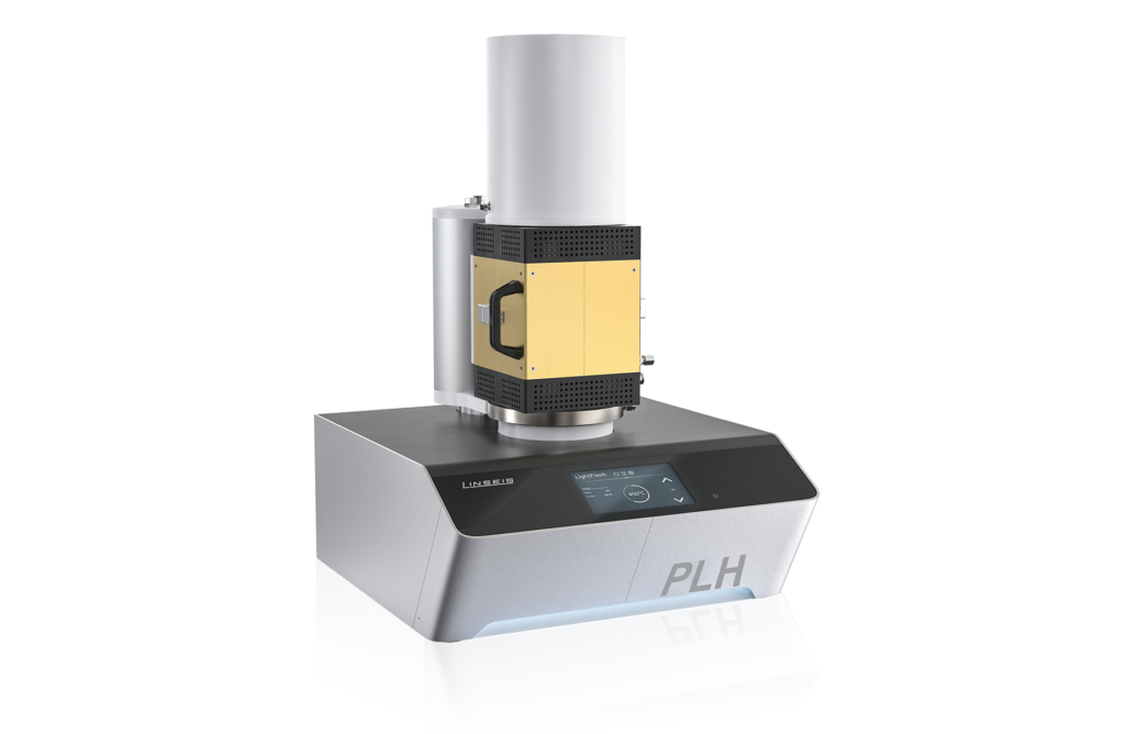

Temperature range
up to 300°C
from 10 µm
up to 500 µm

Multi-Sample robot

Fully automatic
operation
Questions? We're just a call away!
+1 (609) 223 2070
+49 (0) 9287/880 0
Our service is available Monday to
Thursday from 8-16 o’clock
and Friday from 8-12 o’clock.
We are here for you!
Specifications
Hard Facts
MODEL | PLH L53 |
|---|---|
| Temperature range: | RT up to 300°C |
| Heating rate: | 0.01 to 20 °C/min |
| Sample dimensions: | Ø 3, 6, 10, 12.7 or 25.4 mm Square 5×5, 10×10 or 20×20 mm |
| Sample thickness: | 10 – 500 μm |
| Sample robot: | Robot with 3 or 6 samples |
| Laser source: | CW diode laser up to 5 W Wavelength: 450 nm |
| Thermal diffusivity: | 0.01 to 2000 mm²/s (depending on the thickness) |
| Accuracy: | ±5% |
| Repeatability: | ±5% |
| Footprint: | 550 x 600 x 680 mm 21.6 x 23.6 x 26.7 inches |
| STM standards LFA: ASTM E-1461, DIN 30905 and DIN EN 821 ASTM standards PLH: JIS R 7240:2018 & ISO: 20007:2017 |
|
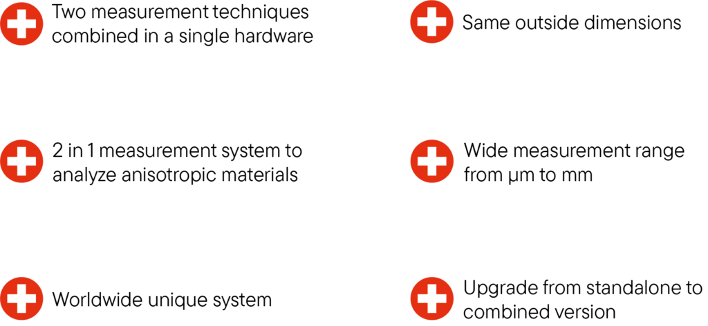
Combination solution LFA + PLH
| Temperature range: | RT up to 300 °C, 500 °C, 1000 °C, 1250 °C, 1600 °C |
| Sample dimensions: | Ø 3, 6, 10, 12.7 or 25.4 mm Square 5×5, 10×10 or 20×20 mm |
| Sample robot: | Carousel with 3 or 6 samples |
| Sample thickness: | 10 to 6000 μm |
| Thermal transmittance: | from 0.01 to 2000 mm2/s (depending on thickness) |
| Accuracy: | ±5% |
| Reproducibility: | ±5% |
Sample holders and carriers
Unchanged samples throughout
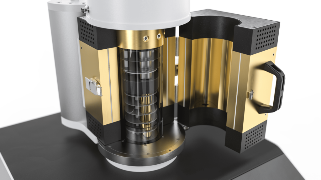
Highest throughput in the market. The combination of sample robot and integrated furnace allows unbeaten measurement turnaround times and fully automized measurements for up to 3 or 6 samples. Depending on the sample requirements various sample holder geometries and materials are available.
Sample carrier
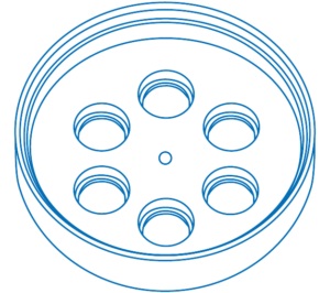
6 samples round or square
3mm, 6mm, 10mm or 12.7mm

3 samples round
25.4mm or square 20mm
Sample holder
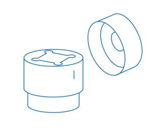
Sample holder square
samples 3×3 mm2 / 10×10 mm2 / 20×20 mm2
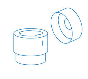
Sample holder round
samples 3mm / 10mm / 12.7mm / 25.4mm
Software
Making values visible and comparable
General
- Brand new design including improved user experience
- Responsive and customizable software
- Direct link to online support
- Periodic online software updates
- Live evaluation as well as post-processing / evaluation
- Advanced storage concepts
- Data export and import in ASCII
- Multi-method measurements (LFA, PLH)
- Data export and import in ASCII
- Customized report generation
- Device Plug & Play
- Easy firmware updates
- Intelligent error handling
- Device connection via USB or LAN
- Plausibility checks before measurement
-
Evaluation Software
- Design update
- Improved user experience and flexibility
- Python-Interface for custom plugins
- Combining curves from different sources / measurement devices
Measurement Software
- Easy and user-friendly data input for temperature
- Fully automated measurement procedure for multi sample measurements
- Specific heat and thermal conductivity measurement routine (requires reference)
Applications
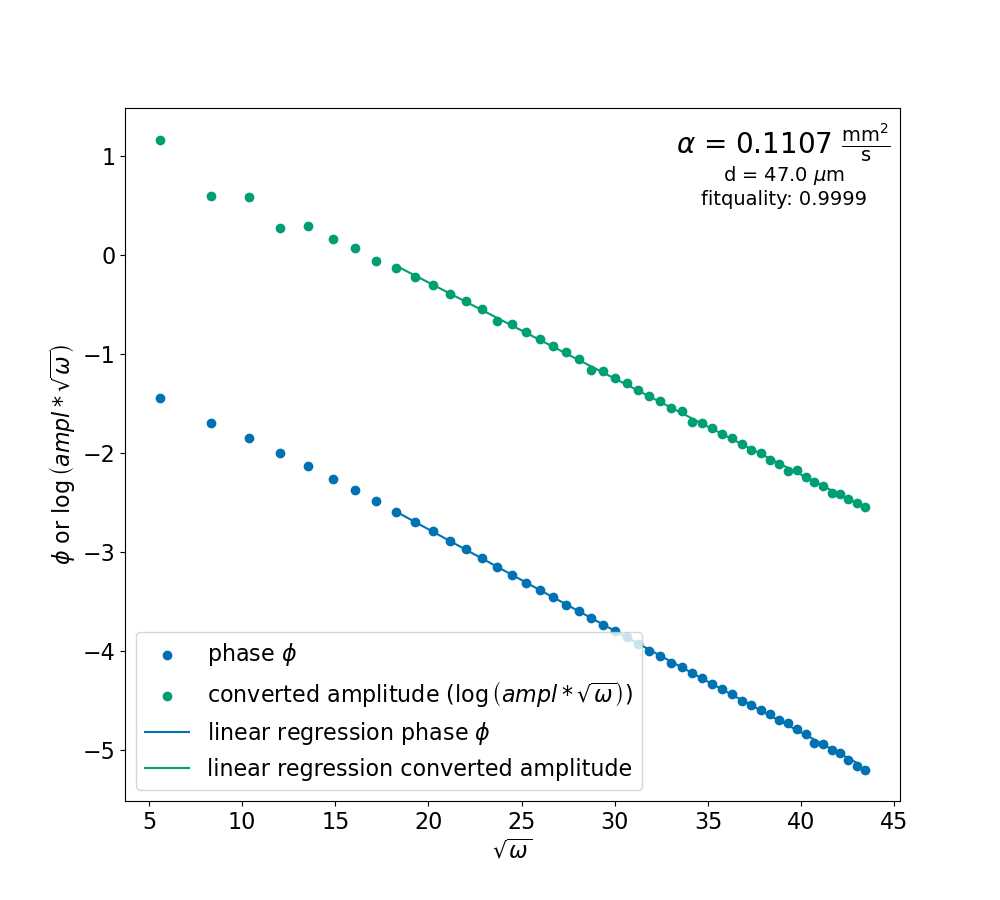
Application: Polytetrafluoroethylene (PTFE) 100 μm
For polytetrafluoroethylene (PTFE) – a thin polymer film – better known as Teflon, the reference value of thermal diffusivity for PTFE is 0.11 mm²/s. Teflon is used as a coating for pans so that food does not stick to the pan and can be easily cleaned. The thickness of these coatings varies from 30 μm to 150 μm.
In the measurement plot on the besides the phase shift between the excitation and the infrared radiation and a somehow amplitude of the infrared radiation vs. the square root of the angular frequency, that is used to drive the laser is pictured. Out of the slope of linear part of these two curves the thermal diffusivity is determined.


Application: Sapphire 500 μm
Sapphire belongs to the category of ceramic materials and has a reference thermal diffusivity value of 13.3 mm²/s. Our measurements confirm this thermal diffusivity value with a high degree of accuracy. As it has excellent thermal and optical properties, it is often used in microelectronics for laser technologies and LEDs.
In the measurement plot on the besides the phase shift between the excitation and the infrared radiation and a somehow amplitude of the infrared radiation vs. the square root of the angular frequency, that is used to drive the laser is pictured. Out of the slope of linear part of these two curves the thermal diffusivity is determined.
Application: Copper 500 μm
Copper foils, especially those as thin as 560 μm, are widely used as heat spreaders in the electronics industry. They play a crucial role in heat dissipation in electronic components by ensuring efficient distribution of heat, which improves the performance and longevity of devices. Their applications range from everyday devices such as smartphones and laptops to sophisticated aerospace systems. The reference value for this sample is 117 mm²/s.
In the measurement plot on the besides the phase shift between the excitation and the infrared radiation and a somehow amplitude of the infrared radiation vs. the square root of the angular frequency, that is used to drive the laser is pictured. Out of the slope of linear part of these two curves the thermal diffusivity is determined.


Application: Repeatability of PTFE 100 μm
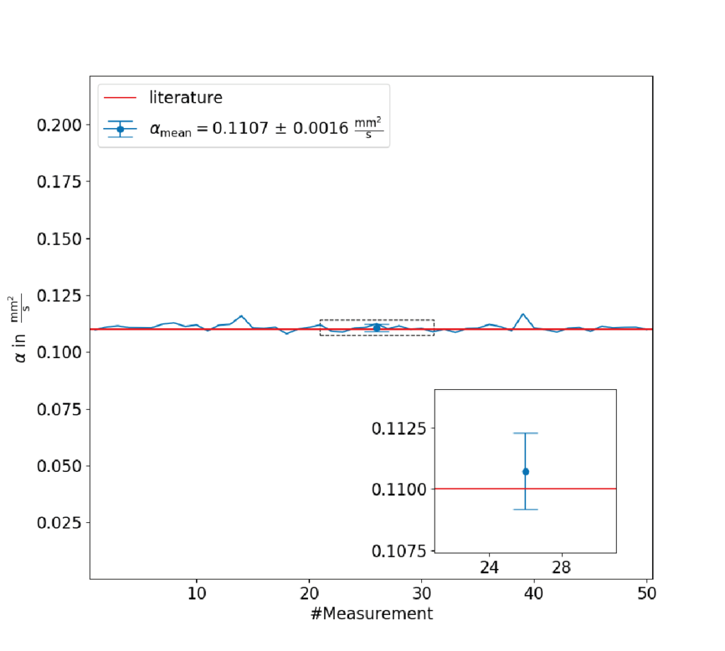
The repeatability of a polytetrafluoroethylene measurement with a thickness of 105.6 μm is excellent, at just over 1%. This confirms the measurement method and its high performance.
Well informed
